
- Aerosol Photometer
- HR-FMS Environment Monitorin...
- Airborne Particle Counters
- Biological Air Sampler
- Air Capture Hood and Anemome...
- Ozone Analyzer
- Differential Pressure Meter
- Temperature and Humidity Met...
- Dust Meter
- Measurement Meters
- GK-01 High Pressure Diffuser
- YWF-01 Fog Generator
- Gelbo Flex Tester System
-
other items
Tutorial on HEPA Filtration
HEPA filters are used in cleanrooms in many differentindustries,including semiconductor, pharmaceutical medicaldevices, nuclear,and biotechnology. The main function of a HEPAfilter is to provideclean air to the cleanroom. The HEPA filter isconstructed with manypleated layers of filter media paper; thisdesign prevents particlesfrom freely passing through the filter asthey become trapped andstick onto the filter fibers (Figure 1).There are four mechanismsat work: capture by straining, impaction,interception, anddiffusion (Figure 2). Straining/sieving isdefined as when aparticle is too large and becomes trapped betweentwo filter fibers.Impaction is when a particle of relativelygreater mass is unable tofollow the curved streamline around thefiber and, as a result ofmomentum, travels in a straight line intothe filter fiber andsticks. Interception occurs when a section ofa particle “runs into”a filter fiber. Diffusion capture occurswhen particles leave thestreamline due to random collisions withthe surrounding fluidmolecules and strike the fibers, where theyagain stick.
LEAK TESTING
ISO 14644-2 outlines the frequency of cleanroom validationaccordingto cleanroom classification. Part of this validationincludes leaktesting of the HEPAfilter. ISO 14644-3 outlines thetestingprocedure to follow.
EQUIPMENT REQUIRED
Aerosol Generator: used to produce an aerosol upstream of theHEPAfilter.A stable test aerosol has particles that have thefollowingdistribution:
- More than 20% by mass of particles less than 0.5 µm
- More than 50% by mass of particles less than 0.7 µm
- More than 75% by mass of particles less than 1.0 µm
An annual output test should be carried out to verify thattheaerosol meets this distribution.
Photometer: used to measure the upstreamaerosolconcentration and downstream penetration of the HEPA filterby theaerosol; it should be calibrated at least annually.
Particle Counter: used to measure the concentrationsofparticles of different sizes downstream of the HEPA filter;itshould be calibrated at least annually.
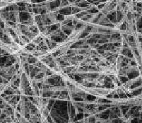
Figure 1: Filter media magnification x500
Figure 2: Filter mechanisms at work
AEROSOL GENERATOR OUTPUT TEST
The aerosol generator output test, carried out annually bythesupplier, verifies that the aerosol generator is capableofproducing a stable distribution.The photometer verifies thatthesensor/optics and flow rates are within tolerances. Somenewdigital photometers now on the market have the ability to verifyon“power up” the condition of the sensor/optics and flow ratesaspart of a self-diagnostics program and, therefore, improvesthereliability of the unit continually instead of waiting annuallyforthe calibration and hoping it passes. Photometer operators canbesatisfied that the photometeris free from contamination aroundthesensor/optics, the flow path is unobstructed,the unit isperformingcorrectly, and that the results are accurate.
TEST METHOD
A linear photometer may be used to measure upstreamconcentrationsprovidedit is calibrated.
This upstream concentration may be used as the 100%reference,enabling percentage penetration downstream to be measureddirectly.The linear photometer may be used to test filters to0.01%.
TEST REQUIREMENTS
Each filter requires an upstream challenge of 20–100 µg/L forbestresults. One must find the area of the filter and theairflowthrough the filter before calculating the throughput of thefilter.The product of throughput and concentration are required togivethe aerosol output required. Alternatively,the aerosol canbeadjusted to reference the photometer at 100%.
TEST PROCEDURE
Disperse the test aerosol upstream of the HEPA filter to produceauniform challenge concentration in the region of 20–100 µg/L.Usingthephotometer, measure the upstream challenge concentration.
Maintain this concentration throughout the test. Adjusttheaerosol generator such that the challenge concentration attheupstream filter face is at a level such that the photometer canbeset and maintained at a stable reading of 100%. The photometeristhen set at 100%.
Using the same photometer, scan the entirety of thedownstreamface and perimeter inclusive of the sealing device withthesampling probe. Hold the probe approx 25 mm away from theareatested and pass over the entire area in slightlyoverlappingstrokes, at a rate of 5 cm/sec. Record the location ofany steady,repeatable reading of the photometer that exceeds 0.01%for gradesA through D in the relevant class of environmentalcleanliness.Refer to ISO 14644-3 section B.6.2.5 for a moredetailed procedure.
GUIDELINES
Care should be taken when generating the upstream aerosol astoomuch aerosolwill over-concentrate the filter and filterreplacementwill be necessary; use too little aerosol and there maybeinsufficient aerosol to effectively scan the filtersufficiently.Discuss these scenarios with to reach anagreementregarding theupstream concentration.
Once a leak has been detected, repair of the filter willbenecessary, following the manufacturer’s procedure regardingthetype of repair media and guidelines on resealing the filterandperforming tests after the repair. After successful testing,aparticle counter positioned under the filter can evaluatethecondition of the filterand can be used as a back up tothephotometer.
References
- ISO 14644-3
- ISO 14644-2
- IEST-RP-CC034
- IEST-RP-CC007
Jason Kelly is the Director of OptiCalSciences,IrelandLtd.and has been working in the semiconductorandpharmaceutical/medical device cleanroom industry for the lasttenyears.He can be reached at www.optical-sciences.ie.
Tutorial on HEPA Filtration
Tutorial on HEPAFiltration
